

머신 비전의 시야: 계산, 시야각 및 흔한 실수
The FOV formula takes three inputs, and it fails for three reasons: nominal sensor names, distortion, and fisheye projection. This guide covers the formula, the angle-of-view relationship, and the checks that keep the numbers honest.

Field of view (FOV) in machine vision is the physical size of the scene the camera captures at a given working distance. For a rectilinear lens it is FOV = (sensor width × working distance) / focal length, a far-conjugate approximation (distance from the entrance pupil in the pinhole model), where sensor width is the active imaging dimension in millimeters, not the nominal format name.
The formula fails when engineers use nominal sensor dimensions, ignore lens distortion, or apply it to fisheye lenses. Verify final numbers with the field of view calculator before ordering hardware.
머신 비전에서 시야각이란 무엇인가요?
Field of view (FOV) in machine vision is the physical area of the scene the camera captures at a given working distance, expressed in linear units at the object plane. A 120mm horizontal field of view means the camera sees a 120mm-wide strip at the inspection distance.
FOV is not a property of the lens alone. It depends on three inputs:
- A longer focal length narrows the field of view.
- A larger active sensor widens the field of view.
- Moving farther from the object widens the field of view.
Change any one of these and the field of view changes, which makes FOV a system-level calculation, not a lens spec lookup. Working distance is a design variable early in a project and fixed once the mechanics are committed. The Commonlands working distance guide covers that tradeoff.

카메라의 시야각은 어떻게 계산하나요?
For a rectilinear lens, horizontal field of view equals active sensor width times working distance, divided by focal length. Use the active sensor dimensions from the camera datasheet, not the nominal format name. The angular projection is anchored at the entrance pupil, not the principal planes or the housing front. In wide-angle and retrofocus designs these points sit many millimeters apart.
Horizontal and vertical coverage use the same relation with the corresponding sensor dimension, and the diagonal follows from Pythagoras. The relation is a far-conjugate approximation, close when the working distance is long compared with the focal length. At short conjugates use thin-lens conjugates: with m = sensor width / scene width, f = WD × m / (1 + m), measured from the object-side principal plane (Hecht, Optics, 5th ed., §5.2).
Use the active imaging width from the camera datasheet, not the nominal format name. A sensor labeled 1/2" has an active width near 6.4mm. Entering 12.7mm (half of 25.4) produces a result nearly double the real field of view.
예제 해설
1/2.3인치 센서의 유효 폭은 약 6.17mm입니다. 6mm 렌즈를 사용하여 300mm의 작업 거리에서:
목표 시야각에 따른 초점 거리 선택
촬영할 장면의 크기를 알고 있을 때 초점 거리를 구하기 위해 식을 다시 정리하십시오:
Round to an available focal length and re-check the coverage: a 12mm lens gives 213mm and a 16mm lens gives 160mm at that distance. The Commonlands focal length selection guide walks through the tradeoff.
Average ground sample distance is FOV_H divided by the pixel column count. It describes sampling, while resolved detail also depends on lens MTF, motion blur, noise, and processing. The Commonlands spatial resolution guide covers how it interacts with lens MTF and pixel size.
화각과 시야각의 차이점은 무엇인가요?
Angle of view is an angular property of the lens and sensor, measured in degrees, and stays effectively constant except at close focus, where focus breathing shifts the effective focal length and distortion, so the angle drifts. Field of view is the physical scene coverage, in millimeters, that the angle produces at a specific working distance on a specific sensor. The two are related by FOV_H = 2 × WD × tan(AoV_H / 2).
| 속성 | 시야각 (AoV) | 시야각 (FOV) |
|---|---|---|
| 단위 | 학위 | 밀리미터, 미터, 또는 인치 |
| 작업 거리에 따라 달라지나요? | Effectively no. Fixed for a lens and sensor pair except at very close focus | Yes. It doubles when working distance doubles |
| 다음에 유용합니다 | 렌즈 사양, 센서 포맷 비교 | 알려진 검사 거리에서의 장면 커버리지 |
Because sensors are rectangular, the angle differs by axis: HFOV uses the active width, VFOV the active height, and DFOV the diagonal. On a 6.3mm × 4.7mm active area, a 4mm lens gives roughly 76° HFOV, 61° VFOV, and 89° DFOV. Datasheets do not always state which axis a quoted angle uses, so check before comparing lenses.
Use the Commonlands angle of view calculator to confirm a lens and sensor combination hits a target angle.
초점 거리와 센서 크기는 시야각에 어떤 영향을 미치나요?
Field of view scales directly with active sensor width and inversely with focal length: doubling the sensor width doubles the FOV, and halving the focal length doubles it. Angle of view responds nonlinearly, so short focal lengths need tighter specification. The same scaling lets pairings match: an 8mm lens on a 2/3" sensor and a 6mm lens on a 1/1.8" sensor give similar horizontal coverage at the same distance.
활성 영역 대 명목상 형식명
Nominal sensor format names are historical designations from tube camera outer diameters. They do not describe the imaging-area size, and using them as dimensions corrupts the FOV calculation:
| 명목 형식 | 일반적인 유효 폭 (mm) | 일반적인 작동 높이 (mm) | 분수 형식을 너비로 사용할 경우 오류가 발생합니다. |
|---|---|---|---|
| 1/4인치 | ~3.6 | ~2.7 | 6.35mm를 사용하면 약 76%의 오차가 발생합니다. |
| 1/3인치 | ~4.8 | ~3.6 | 8.47mm를 사용하면 약 76%의 오차가 발생합니다. |
| 1/2.3인치 | ~6.17 | ~4.55 | 11.04mm를 사용하면 약 79%의 오차가 발생합니다. |
| 1/2인치 | ~6.4 | ~4.8 | 12.7mm를 사용하면 약 98%의 오차가 발생합니다. |
| 1/1.8인치 | ~7.18 | ~5.32 | 14.11mm를 사용하면 약 97%의 오차가 발생합니다. |
| 2/3인치 | ~8.8 | ~6.6 | 16.93mm를 사용하면 약 92%의 오차가 발생합니다. |
Active dimensions vary by manufacturer and pixel count within a nominal format, so check the specific camera model. The CMOS sensor size guide explains the naming convention, and the Commonlands image sensor reference lists active dimensions for common sensors.
왜 왜곡, 어안 투영, 이미지 서클이 실제 답을 바꾸게 되는 것일까요?
The rectilinear FOV formula assumes straight lines map to straight lines on the sensor. Barrel distortion and fisheye projection depart from that mapping. An undersized image circle is a separate coverage problem that can clip the field or leave the corners too dark or soft.
Barrel Distortion Splits Coverage Into Raw and Usable
Barrel distortion makes the formula answer two questions with one number, so read its result against the quantity you care about:
| 수량 | What barrel distortion does | Formula error |
|---|---|---|
| Total angular field | Local magnification falls with field height, so the lens sees more scene than a rectilinear lens of the same focal length | Understates the true angular coverage |
| Usable low-distortion region | Geometry stays accurate only over a smaller central radius | Overstates the coverage you can measure on |
| Edge pixel scale | Each edge pixel covers more scene, so a rectified image must stretch the edges back out | Understates the scene width each edge pixel spans |
Many standard machine vision lenses approximate rectilinear projection closely enough that the gap is small. Departure from that model depends on projection and distortion correction, not focal length alone, and wide-angle designs show it most. Treat the formula result as a rectilinear reference field. The true raw field follows the measured projection and distortion curve. Derate for the low-distortion region the task needs, and specify low-distortion lenses for measurement or alignment. The Commonlands low distortion lens guide covers how they are specified.
피쉬아이 렌즈는 완전히 다른 계산 방식이 필요합니다
Fisheye lenses do not follow the rectilinear model. They use alternative projections such as equidistant, equisolid, stereographic, or orthographic mapping. The sensor-size-to-angle arctan formula must be replaced with the appropriate projection model. Once the actual boundary-ray angle is known, W = 2d tan(θ/2) still gives coverage on a centered plane perpendicular to the optical axis for a symmetric field below 180°. Fields at or above 180° have no finite width on that plane. Common fisheye mappings include:

A 180° fisheye images a 90° half-angle cone, and converting that to a scene width needs the projection function, not the tan formula. Use the manufacturer's mapping data, which the Commonlands fisheye and wide-angle distortion guide treats in depth.
이미지 서클과 센서 크롭
Lenses project a circular image. If the sensor diagonal exceeds the lens image circle, the corners vignette or degrade first. The horizontal and vertical edges lose coverage only if the circle cuts inside the sensor's width or height, set by circle diameter and sensor aspect ratio. If the image circle is larger than the sensor, the sensor crops the projection: a lens rated for 2/3" sensors on a 1/2" sensor sees a narrower angle than its datasheet states.
Verify the image circle covers the sensor diagonal, and calculate with your sensor's active dimensions. The Commonlands sensor size and lens compatibility guide covers both failure modes.
어떤 렌즈들이 광각, 표준, 협각 시야를 모두 커버하나요?
Focal lengths from 2.6mm to 25mm produce horizontal fields of view from roughly 712mm down to 74mm at 300mm working distance.
시야각 대역별 최고 렌즈 순위
These five Commonlands lenses span the range at a fixed working distance, ranked widest to narrowest, from the CIL227 190° fisheye to the CIL250 25mm telephoto.
| FOV 대역 | 렌즈 | 마운트 / EFL | 보도된 기사 | 최적의 적용 사례 |
|---|---|---|---|---|
| 초광각 어안 렌즈 | CIL227 2.7mm 어안 렌즈 | M12, 2.7mm | 8.0mm 이미지 서클에서 190° 시야각 (등거리 투영법) | 보안, 드론 및 존재 감지를 위한 반구형 커버리지 |
| 넓은 | CIL059 6mm 저왜곡 | M12, 6mm | 76° FOV at an 8.8mm reference circle | Wide coverage. −4% Rectilinear needs calibration before measurement |
| 넓은 | CIL062 6.2mm | M12, 6.2mm | ~347mm at 300mm WD on a 1/1.8" sensor | Budget coverage at −2% rectilinear distortion. Calibrate before gauging or alignment |
| 중간 | CIL531 8mm C-마운트 | C-마운트, 8mm | 2/3인치 센서에서 초점 거리 300mm 시 약 330mm (~58° 수평 화각) | 12MP 2/3인치 센서의 가변 조리개 심도 제어 |
| 협각 망원 | CIL250 25mm 망원 렌즈 | M12, 25mm | 1/2.3인치 센서에서 초점 거리 300mm, 후면 거리(WD) 약 74mm (~14° 수평 시야각) | 더 긴 작업 거리에서의 미세 특징 검사 |
Coverage figures come from the 300mm scene-coverage table later in this section or the lens product-page datasheet. The fisheye value is equidistant-projection coverage, not a rectilinear formula result.
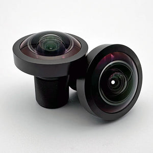
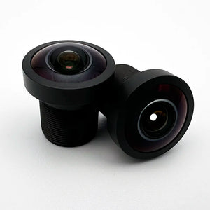
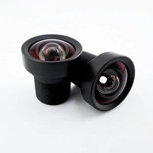
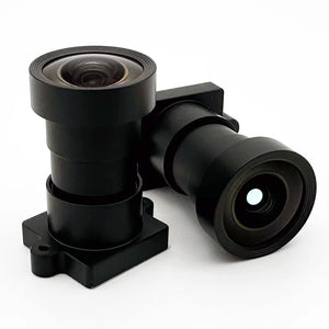
300mm 작업 거리에서 초점 거리가 장면의 촬영 범위에 미치는 영향
This Commonlands reference table shows approximate horizontal field of view for rectilinear lenses at 300mm working distance on common sensor formats. All values use active sensor widths.
| 초점 거리 | 센서 형식 | 유효 폭 (mm) | 300mm WD에서의 FOV_H (mm) | 보장 범주 |
|---|---|---|---|---|
| 2.6mm | 1/2.3인치 | 6.17 | ~712 | 매우 넓음 |
| 6mm | 1/2.3인치 | 6.17 | ~309 | 표준 |
| 6mm | 1/1.8인치 | 7.18 | ~359 | 표준 (더 큰 센서) |
| 8mm | 2/3인치 | 8.8 | ~330 | 표준 (C-마운트) |
| 25mm | 1/2.3인치 | 6.17 | ~74 | 망원 / 좁은 |
The C-mount row adds an adjustable iris, so stopping down extends depth of field when a target field of view also carries a depth requirement.

자주 묻는 질문
머신 비전에서 시야각이란 무엇인가요?
머신 비전에서 시야각(FOV)이란, 주어진 작동 거리에서 카메라가 포착하는 장면의 물리적 영역을 말하며, 물체 평면에서 밀리미터 단위로 측정됩니다. 수평 시야각이 120mm라는 것은 카메라가 해당 거리에서 폭 120mm의 띠 모양 영역을 인식한다는 의미입니다. 시야각은 초점 거리, 유효 센서 크기, 작동 거리의 조합에 따라 결정됩니다.
머신 비전의 시야각은 어떻게 계산하나요?
For a rectilinear lens: FOV_H = (sensor width × working distance) / focal length, all in millimeters, a far-conjugate approximation (distance from the entrance pupil in the pinhole model). Use the actual active sensor dimensions, not the nominal format name. A 1/2" sensor has an active width of approximately 6.4mm, not 12.7mm. To find the focal length for a target FOV, rearrange: f = (sensor width × working distance) / target FOV. Fisheye and high-distortion lenses need a projection-corrected calculation.
광각 렌즈와 어안 렌즈는 왜 단순한 시야각(FOV) 계산식을 깨뜨리는가?
표준 공식은 직선 투영을 가정하며, 이 경우 장면 내의 직선이 센서상의 직선으로 매핑됩니다. 배럴 왜곡이 있는 광각 렌즈는 이미지 가장자리를 압축하기 때문에, 왜곡이 없는 유효 촬영 범위는 공식으로 예측된 값과 다릅니다. 피쉬아이 렌즈는 완전히 다른 투영 모델(등거리 또는 등체적)을 사용하기 때문에, arctan 및 tan 공식은 전혀 적용되지 않습니다.
수평 화각, 수직 화각, 대각선 화각의 차이점은 무엇인가요?
Horizontal AoV (HFOV) uses the active sensor width, vertical AoV (VFOV) uses the active sensor height, and diagonal AoV (DFOV) uses the sensor diagonal. For a rectangular sensor, DFOV is the largest of the three. Lens datasheets may quote any axis without saying which, so check before comparing lenses. DFOV can exceed VFOV by more than 30 degrees on a 16:9 sensor.
목표 시야각에 따라 초점 거리는 어떻게 선택해야 하나요?
Rearrange the FOV formula, a far-conjugate approximation with distance from the entrance pupil in the pinhole model: f = (sensor width × working distance) / target FOV, all in millimeters. Start from the active sensor width in the camera datasheet, the working distance your system geometry dictates, and the required scene coverage. Round to the nearest available focal length, then verify the resulting FOV with the Commonlands field of view calculator before ordering hardware.
목표 시야 범위를 맞추는 데 도움이 필요하신가요?
Commonlands US-based optical engineers can review your sensor, working distance, and inspection geometry and recommend a specific lens. ISO 9001:2015 certified. Orders placed before 12 PM PST ship the same day from San Diego.