

What Is an F-theta Lens? Scan Lenses for Galvo Laser Marking and Engraving
An F-theta lens is a scan lens for galvo-based laser marking and engraving systems. It maps scan angle to image height linearly, r = f·θ, so a galvo sweeping at constant angular velocity moves the focused spot at constant linear velocity across a flat work plane.

An F-theta lens is a flat-field scan lens placed after a galvanometer mirror pair in laser marking, engraving, and material processing systems. Its defining relationship is r = f·θ (image height linear in scan angle), which converts the galvo's nominally constant angular velocity into constant linear velocity at the work plane. Keeping the beam in focus across the full scan field is a separate property, flat-field correction, which the same design has to solve alongside the mapping.
That is a different device and design problem from a rectilinear machine vision imaging lens (r = f·tan(θ)) or a fisheye camera lens. Commonlands manufactures M12 and C-mount imaging lenses, not F-theta scan lenses. This article is an engineering reference on scan-lens physics.
What does r = f·θ mean in an F-theta lens?
The relationship r = f·θ defines an F-theta scan lens. Here r is the radial distance of the focused spot from the center of the scan field, f is the effective focal length of the scan lens, and θ is the scan angle measured at the lens, in radians. Image height is proportional to angle rather than to its tangent.
The F in F-theta is the focal length f, not an aperture number. Engineers often misread the leading F as an aperture prefix.
A galvanometer scanner rotates a small mirror through a mechanical angle. A flat mirror deflects the beam by twice its own rotation, so along one axis the optical scan angle θ reaching the lens is twice that mirror's mechanical travel.
A marking head uses two mirrors, and the pair does not reduce to two independent doublings: they sit at different distances from the lens, the first deflection strikes the second mirror at a varying angle, and the two field coordinates couple. Controllers map commanded angles to work-plane position through a correction table rather than one formula.
Because the mapping is linear in θ, a step from 2° to 4° of optical scan angle produces the same spot displacement as a step from 10° to 12°. That constant ratio, together with the flat-field correction covered below, is what the F-theta design exists to deliver.
A typical galvo marking head is laid out in this order: laser source, beam expander, galvanometer mirror pair (X, Y), F-theta scan lens, work plane. The F-theta lens is the last optical element before the material, and it turns scan angle into position and focus at the work surface.

Why do laser scanning systems need linear scan position?
A galvanometer mirror holds a commanded angular velocity through the steady part of a marking stroke, so the controller can place dots, vector strokes, or raster lines at a predictable rate. Real motion adds acceleration and deceleration at each stroke end, and controllers carry correction tables and timing offsets for the residual, so constant angular velocity describes the mid-stroke case rather than the whole move.
Through that steady stretch, r = f·θ turns a constant dθ/dt into a constant dr/dt at the work plane, since dr/dt = f·(dθ/dt). Line speed, dwell time per unit length, and dot spacing then stay uniform from field center to edge.
Uneven line speed changes the energy deposited per unit length, showing up as inconsistent mark depth or contrast. Without a matched lens the spot runs slow at center and fast at the edges, which is why these lenses are specified by focal length and scan angle together.
A linear mapping also simplifies the scan controller: it commands mirror angle as a linear function of desired position and lets the lens hold that linearity optically, rather than solving for position at every field point.
What is the flat-field requirement in an F-theta lens?
A flat-field lens holds the focused spot in focus across a flat work plane, not across the curved focal surface a simple lens produces. An F-theta scan lens must do this on top of the r = f·θ mapping, because marking needs correct spot position and correct focus everywhere in the scan field.
Without correction the best-focus surface is curved rather than flat. The Petzval sum over element powers and refractive indices sets that curvature, and astigmatism splits the tangential and sagittal focal surfaces around it. Which way the surface bows follows from the prescription and the sign conventions in use, not from a universal rule: an all-positive design gives the familiar inward curve, and negative-power elements can flatten or reverse it.
A flat work surface meets a curved focal surface at one radius, so focus is sharp there and degrades away from it. An F-theta design distributes element powers, commonly including negative elements, to drive the Petzval sum toward zero and hold focus across the full scan angle.
The flat-field correction and the r = f·θ angular linearization are solved together in the same optical design. A lens that achieves one without the other is not a usable F-theta scan lens.
For background on field curvature as an off-axis aberration, see the Commonlands guide to lens aberrations in machine vision. It is the same aberration, discussed there for imaging lenses rather than scan lenses.
How does F-theta differ from rectilinear projection?
Rectilinear projection, used by machine vision and photographic imaging lenses, follows r = f·tan(θ) to keep straight scene lines straight in the image, the property dimensional inspection and measurement depend on. F-theta scan lenses follow r = f·θ to linearize a moving spot's position against mirror angle on a flat work surface. They are built to place a spot, not to image a scene onto a sensor.
Relative to the rectilinear ideal, r = f·θ maps every off-axis point closer to the field center than r = f·tan(θ) would, so an F-theta lens carries a controlled barrel (negative) distortion on purpose. F-theta error on a scan-lens datasheet is the percentage deviation from that ideal r = f·θ curve, not from a rectilinear one.
The mapping alone does not rule a scan lens out as a camera lens. Fisheye camera lenses use the same one and image scenes well. A scan lens images poorly for other reasons: it is corrected for collimated input at a single laser wavelength, its pupil sits at the galvo mirrors rather than where a camera needs it, its conjugates and field are fixed by the scan geometry, and it carries no iris or sensor mount.
| 속성 | Rectilinear imaging lens | F-theta scan lens |
|---|---|---|
| Mapping formula | r = f · tan(θ) | r = f · θ |
| 기능 | Forms a photographic image of a scene onto a sensor | Positions and focuses a scanned laser spot on a flat work plane |
| Design goal | Preserve straight scene lines. Minimize distortion at the sensor | Linearize spot position vs. galvo angle. Flatten focal surface |
| Input | Ambient or structured light from a scene | A single-wavelength, pre-conditioned laser beam |
| Practical field limit | Hard limit below a 180° full field: r = f·tan(θ) diverges as θ approaches 90°. Edge stretch grows continuously and dominates well before that | Typically a rated scan angle in the 20–50° full-angle range for a given focal length |
| 대표적인 적용 사례 | Machine vision, inspection, robotics cameras | Laser marking, engraving, cutting, material processing |
Neither lens type substitutes for the other. A Commonlands M12 or C-mount lens inspecting a part after laser marking has no scan-angle linearization requirement: it images a static scene, a different job on the same production line.
What is a telecentric F-theta lens?
A telecentric F-theta lens adds image-side telecentricity so the focused beam strikes the work plane close to normal everywhere in the scan field, rather than at an incidence angle that grows toward the edges. Telecentricity here is a specified residual: datasheets state a maximum chief-ray angle over the field, a small number rather than exact perpendicularity. In a standard F-theta lens that angle is not held small, so the chief ray meets the work surface increasingly off-axis toward the edges.
The payoff is spot and kerf consistency (kerf is the width of material the beam removes): at a near-constant, near-normal angle, projected spot size, kerf width, and depth profile stay more even from center to edge. That matters for processes sensitive to angle of incidence, such as precision cutting or fine engraving on reflective materials, more than for coarse marking.
These lenses are larger and more complex than standard designs, since telecentricity across a wide scan angle needs extra elements with larger apertures near the work-plane side.
Is an F-theta lens the same as a fisheye lens?
No. An F-theta scan lens and a fisheye camera lens can share the same angle mapping, r = f·θ (equidistant projection), but they solve different problems. An F-theta lens directs a scanned laser spot from a galvo pair onto a flat work plane. A fisheye lens forms a wide-angle image of a static scene onto a sensor. Equidistant projection is one of several fisheye models, alongside equisolid and stereographic. The Commonlands fisheye and wide-angle lens guide explains those imaging projections. This article covers laser scanning.
The same formula also shows up in catalog data. Some M12 wide-angle camera lens datasheets, including entries in the Commonlands catalog, label a distortion value "F-theta" or "F-Θ" as a percentage deviation from the ideal equidistant curve. That describes the camera lens's distortion profile. It is not a claim that the lens is a laser scan lens.
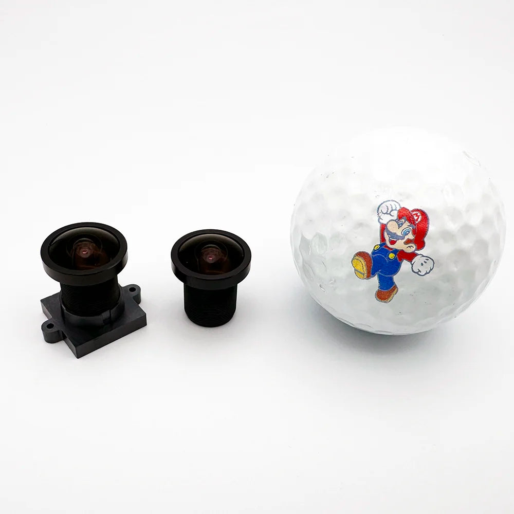
Commonlands' CIL926, a 2.5mm M12 wide-angle imaging lens rated at 172° field of view on a 7.4mm image circle, reads "F-Θ" in its datasheet distortion field. That is standard practice for characterizing wide-angle and fisheye distortion. It says nothing about scan-field linearization or flat-field correction for a moving laser spot.
F-theta scan lens specification reference
F-theta scan lenses for fiber and CO2 laser marking systems are specified by focal length, scan angle, wavelength, and spot size, not by the sensor-format and mount conventions used for machine vision imaging lenses. The table below is general industry information, not a Commonlands product line.
| Effective focal length | Typical scan field side | Common use case |
|---|---|---|
| 100mm–160mm | Roughly 70mm–110mm | Fine marking, small-part serialization, micro-engraving |
| 160mm–255mm | Roughly 110mm–180mm | General-purpose marking and engraving |
| 330mm–460mm | Roughly 220mm–330mm | Large-area marking, panel processing, coarser cutting |
All three rows above assume roughly a ±20° optical scan angle (about 40° full field). The scan field side then follows scan field ≈ 2 × f × θ, with θ in radians (±20° ≈ ±0.35 rad). Rate a lens for a wider or narrower scan angle and the field size scales with it.
Scan field size, spot size, and edge performance trade against each other for a given aperture and mirror size: a longer focal length covers more area at the same mirror angle. At fixed input beam diameter and wavelength, it also increases the diffraction-limited spot size. Field-edge aberrations depend on the prescription and scan geometry.
Wavelength matters because F-theta lenses are typically optimized for a single laser wavelength, commonly 1064nm for fiber lasers or 10.6µm for CO2 lasers. A lens optimized for one wavelength degrades at a substantially different one and may need a different design. Small offsets within the design band are usually tolerable.
Commonlands does not sell F-theta scan lenses. They come from laser system integrators and scan-optics manufacturers, matched to a specific galvo scanner, wavelength, and beam diameter. They are not interchangeable the way a machine vision lens sometimes is between similar cameras. Confirm scan angle, working distance, and wavelength with the scanner and laser manufacturer before specifying a replacement.

Frequently asked questions about F-theta lenses
What is an F-theta lens?
An F-theta lens is a scan lens used after a galvanometer mirror pair in laser marking, engraving, and material processing. It follows r = f·θ, mapping image height linearly to scan angle, and holds the focused spot on a flat work plane across the scan field, not on a curved surface.
Why does F-theta projection matter for laser scanning?
Galvo mirrors run at nominally constant angular velocity during a marking stroke. With r = f·θ, equal steps in mirror angle produce equal steps in spot position, so constant angular velocity gives constant linear velocity at the work plane. Without it, the spot would move slower near the center and faster toward the edges.
What is a telecentric F-theta lens?
A telecentric F-theta lens adds image-side telecentricity so the focused beam strikes the work plane close to normal across the scan field, rather than at angles that grow toward the field edges. Telecentricity is specified as a small residual chief-ray angle over the field, not as exact perpendicularity. Holding that angle small keeps spot size and kerf geometry consistent edge to edge.
Is an F-theta lens the same as a fisheye camera lens?
No. Both can involve an equidistant angle mapping, but an F-theta lens projects a moving laser spot onto a flat work plane in a marking system, while a fisheye camera lens forms a wide-angle image of a scene onto a sensor. The r = f·θ formula appears in both. The application, the flat-field requirement, and the design constraints differ.
Why does Commonlands catalog data show "F-theta" or "F-Θ" on some M12 camera lenses?
Commonlands uses "F-theta" or "F-Θ" in some M12 wide-angle lens datasheets as shorthand for an equidistant-style distortion profile, the same r = f·θ relationship used to describe fisheye camera lenses. It labels a camera lens's distortion behavior, a different use of the term from the F-theta scan lens used in laser marking that this article covers.
What focal length range do F-theta scan lenses typically cover?
Commercial F-theta scan lenses for fiber and CO2 marking systems span effective focal lengths from well under 100mm to roughly 400mm or more. Focal length and the rated scan angle together set the scan field size, roughly 2 × f × θ with θ in radians. Shorter focal lengths give a smaller, tighter scan field. Longer ones cover a larger area at the cost of spot size and edge performance.
Need machine vision optics for a laser processing line?
Inspection and alignment cameras around a marking station use a standard rectilinear lens, not an F-theta scan lens. Commonlands builds M12 and C-mount imaging lenses for those roles. Size one to your part with the field-of-view calculator, then talk to our engineering team or request samples to verify fit.