Barcode and data-capture optics

Barcode Reading in Machine Vision: A Lens Guide for OCR, Document Scanning, and Biometrics

Pixel coverage, depth of field, and distortion control for reading codes, characters, pages, and faces: the optical margin that decoding software depends on.

By the Commonlands engineering team · Updated July 2026 · 24 min read

A board-level M12 camera reads 1D barcodes and Data Matrix codes on a conveyor

Barcode reads, OCR, document scans, and biometric captures all fail for the same reason before software ever runs: the optics did not deliver enough pixels, sharp focus, or clean geometry on the feature that matters. Each task sets a different minimum: roughly 10 pixels per bar for 1D codes, 8 pixels per module target (6 px marginal lower bound) for 2D codes, 20 pixels across a character's x-height, and 100 or more pixels across an iris diameter for biometric capture. Fix the pixel-coverage target first, then verify depth of field, distortion, and illumination against the real working distance.

What data-capture reading needs from the optics

A decoder reads contrast differences between bars and spaces, between dark and light modules, between character strokes and background, or between iris texture and sclera. The optical system must deliver those contrast differences to the sensor with enough resolution to distinguish adjacent elements. When it does not, decode rate and match accuracy both drop, regardless of how good the downstream algorithm is.

The optical requirements break into five categories that apply across barcode, OCR, document, and biometric capture alike.

Pixel coverage of the smallest feature

The decoder needs a minimum number of pixels across the narrowest element to distinguish it from its neighbors. For 1D barcodes that element is the X dimension, the narrowest bar or space. For 2D Data Matrix and QR codes it is the module size. For OCR it is character x-height. For iris biometrics it is the iris diameter. Under-sampling this feature is one of the most common root causes of read failures in new installations across all four applications.

Contrast transfer at the spatial frequency of the feature

Even with adequate pixel coverage, a lens with poor MTF at the feature's spatial frequency reduces edge sharpness. This is a lens MTF problem, not a pixel-count problem. Specifying a lens by resolution class (megapixel rating) alone is not sufficient. Check that MTF at the spatial frequency of the narrowest bar, module, or stroke remains above roughly 20-30% at the sensor plane.

Depth of field across the real working-distance range

Parts on a conveyor, documents on a platen, and faces at a kiosk are rarely at a perfectly fixed distance. Conveyor sag, stacked labels, curved packaging, book curvature, and natural stand-off variation in front of a camera all create working-distance variation the lens must stay in focus across. The practical tolerance for reading and decoding tasks is 1 pixel of circle of confusion at the sensor. Use the depth of field calculator with that tolerance to find the usable depth of field for a given lens, aperture, and pixel pitch.

Controlled distortion across the usable field

Distortion deforms bars, modules, characters, and facial or iris geometry near the edges of the image. Near the center of the frame, distortion effects are small and most decoders and matching algorithms tolerate them. Near the edges, barrel or pincushion distortion can warp geometry enough to fail a decode or degrade a biometric match. A low-distortion lens reduces this risk and reduces the geometric correction burden that would otherwise fall on software.

Illumination and exposure matched to the task

At production line speeds, long exposure times smear bars and characters across multiple pixels. A 250mm/s conveyor moving during a 2ms exposure creates 0.5mm of motion blur. If the bar width is 0.3mm and each pixel covers 20 microns in the scene, that blur destroys edge information entirely. For biometric and document capture, the constraint shifts from motion blur to illumination uniformity and, for iris imaging, to a specific NIR wavelength. In every case, the exposure time and illumination design must be sized to the lens aperture and the feature being resolved, not treated as an afterthought once the lens is chosen.

Insight

Before adjusting decoder parameters, retraining an OCR model, or tuning a biometric matcher, verify that the optical system delivers the pixel coverage, contrast, depth of field, and illumination the algorithm actually needs at the real working conditions. Optical margin problems look like software problems until someone measures pixels per feature.

An M12 lens images a Data Matrix code etched into a metal part
Low-angle light brings out dot-peen marks for direct part mark reading.

How 1D barcodes, 2D Data Matrix and QR codes, and direct-part-mark codes differ

Different code types place different demands on the optics and illumination. Understanding those differences before selecting a lens avoids mismatched system design.

1D barcodes (Code 128, GS1-128, Code 39, ITF-14)

One-dimensional barcodes encode data in bars along a single axis. The decoder reads a single scan line across the code and measures the widths of bars and spaces, so the lens only needs to resolve the code along the reading axis. Blur perpendicular to the bars is tolerable. The key parameter is the X dimension (narrowest bar width) and how many pixels it occupies at the working distance and field of view. Production-grade 1D labels commonly have X dimensions from 0.25mm on small labels to 1mm or more on pallet-scale codes. A tighter X dimension requires more magnification, more pixels per unit length, or a narrower field of view.

2D Data Matrix and QR codes

Two-dimensional codes store data in both axes simultaneously, and every module must be individually resolvable in both directions. This raises the bar on several optical properties: the lens must maintain adequate MTF across the full field, not just at the center; edge distortion becomes a real failure mode rather than a cosmetic issue; and focus must be uniform across the entire code footprint. QR codes include alignment markers that help decoders correct for moderate perspective and rotation, giving them slightly more geometric tolerance than Data Matrix.

Direct-part-mark (DPM) codes

DPM codes are laser-etched, dot-peened, or chemically etched directly on metal parts. Contrast comes from surface texture rather than ink density, which is much lower than a printed label. This places two constraints on the optics: MTF at the module spatial frequency must stay high (and the aperture must not be so small that diffraction reduces contrast at that frequency), and illumination design (angled, dark-field, or coaxial with a polarizer) often has to make the shallow surface features visible in the first place. The optics must be compatible with the illumination approach chosen.

A comparison of common failure modes

Failure symptom Likely optical cause First parameter to check Likely fix
Decode fails only near image edges Distortion or off-axis aberrations Distortion spec and edge MTF at the field coverage in use Use a lower-distortion lens; keep the code within the usable image circle
Decode fails at line speed but passes static Motion blur from long exposure Exposure time vs conveyor velocity in mm/s Reduce exposure time; add brighter or strobed illumination
Decode fails across a range of distances Depth of field too shallow Aperture setting vs 1-pixel CoC budget at the sensor Stop down within the diffraction limit; increase illumination to compensate
Intermittent failures on small codes or characters Pixel coverage below minimum threshold Pixels across the narrowest bar, module, or character height Reduce field of view, use a longer focal length, or move the camera closer
Decode fails only on shiny labels or metal DPM Specular glare washing out contrast Illumination angle and specular reflection geometry Switch to diffuse or angled illumination; add a bandpass filter matched to the LED source

How to choose the focal length and working distance for barcode reading

Focal length and working distance together determine the field of view, which sets the pixel density on the code. Getting this relationship right is the first step in barcode lens selection, and the same formula applies to OCR and document scanning further down this page.

EFL = (WD × sensor dimension) / FOV EFL = effective focal length (mm) | WD = working distance (mm) | sensor dimension and FOV in mm, same axis

This relationship is exact for rectilinear projection (Hecht, Optics, 5th ed., §5.2). It is not a thin-lens approximation. For distortion-corrected values at wide fields of view, use the field of view calculator or the EFL calculator.

A worked example: label reading on a packaging line

A camera with a 1/2.3" sensor (6.17mm × 4.55mm active area) needs to read a label 60mm wide at a working distance of 400mm. The required FOV width is 60mm, so the needed EFL is approximately 400 × 6.17 / 60 = 41.1mm. With 4000 pixels across the sensor's 6.17mm width, each pixel covers 60mm / 4000 = 0.015mm in the scene. A 0.25mm X-dimension bar at that coverage gives 0.25 / 0.015 = 16.7 pixels per bar, above the 10-pixel production target.

Design rule

Choose the focal length that puts pixel coverage at 1.5-2× the minimum threshold at the nominal working distance. That margin absorbs working-distance variation, slight defocus, and real-world MTF that runs below the datasheet number.

Fixed focal length lenses versus zoom lenses

Fixed-focal lenses are the correct default for data-capture reading when working distance is controlled. They cost less, deliver better MTF uniformity across the field for a given price, and eliminate focal length drift over time. Zoom lenses are useful during development or when the working distance or target size changes by design, but they need the zoom position locked before production.

Working distance ranges for M12 and C-mount lenses

M12 lenses are typically usable from about 50mm to infinity, uncorrected; the practical range varies by lens model. C-mount lenses vary by product and are typically usable from about 100mm to infinity (for example, the CIL522 12mm C-mount). For very close-range reading on small electronics, check each lens model's minimum object distance specification, measured from the front of the lens to the object; not every datasheet publishes it. See the minimum detectable size guide for how pixel coverage and field of view interact at close range.

Lens selection for OCR and character reading

OCR decodes characters by analyzing stroke contrast, edge sharpness, and the spatial relationships between strokes. It is an optics margin problem before it is a software problem: if characters do not occupy enough pixels, if focus is soft, or if motion blur has smeared stroke edges, no OCR engine reliably reconstructs what was never captured.

The priority order for OCR lens selection is pixel density first, then focus across the scene's depth variation, then contrast and motion blur, and distortion control last. A common integration mistake is worrying about distortion before confirming the first three.

Pixel density and the 20-pixel rule

A practical threshold is at least 20 pixels across the x-height of the smallest character to be read. Below 10 pixels per character height, accuracy collapses for most engine and font combinations regardless of the rest of the optical system. To check a design: take the sensor pixel count in the relevant axis, multiply by character height as a fraction of the scene dimension in that axis, and compare to 20. A 1920-pixel vertical axis capturing an 80mm scene with 4mm-tall characters gives 1920 × (4/80) = 96 pixels per character, well above the threshold. At 0.8mm characters in the same scene, coverage drops to 19 pixels, which is marginal. The fix is a longer focal length or a higher-resolution sensor, not a different OCR engine.

Depth of field and motion blur

Out-of-focus images degrade stroke contrast at exactly the edges OCR depends on; even mild defocus that looks acceptable to a human eye can drop contrast below the threshold for reliable segmentation. Depth of field must cover the full range of character distances in the scene. If parts vary in height by 15mm, confirm the lens holds acceptable contrast across that range at the working aperture. A C-mount lens with an adjustable iris can stop down to recover depth of field when illumination is controlled, which most M12 lenses cannot do since they typically do not provide an adjustable iris. Motion blur is a separate failure mode: a character moving at 200mm/s during a 4ms exposure travels 0.8mm, enough to smear a 1mm stroke significantly, so shutter speed and conveyor speed must be checked together.

When a longer focal length helps OCR

Longer focal lengths become useful when the camera cannot move closer and a shorter lens would produce characters too small to resolve: license plate reading, text on packages passing under an overhead camera, or serial numbers on parts at a fixed robotic-arm distance. Depth of field decreases as focal length increases, and sensitivity to vibration increases too, so verify both before committing to a longer lens in a production environment. When installation geometry allows it, moving the camera closer and using a shorter focal length is usually better: more depth of field, less vibration sensitivity, and more lens options.

When low distortion matters for OCR

Distortion matters most when the spatial arrangement of characters encodes meaning (grids of characters, fixed-format multi-line text) or when the same camera is calibrated for measurement alongside reading. Most OCR engines handle a few percent of edge distortion without explicit calibration because they process individual characters, not spatial relationships between them. Low distortion does not substitute for adequate pixel density or sharp focus: a lens with 0.4% distortion and enough pixels per character will typically outperform a 0.1%-distortion lens that puts the text at the edge of its depth of field.

Choosing between M12 and C-mount for OCR

M12 lenses fit most compact OCR deployments: embedded cameras reading barcodes or labels at fixed working distances, and any setup where space rules out a C-mount body. A low-distortion M12 lens such as the CIL052 provides -0.1% rectilinear distortion, more than adequate for label reading and character recognition. Because M12 aperture is fixed, the system must be designed around that f-number for depth of field and exposure time. C-mount becomes the better choice when depth-of-field control is critical (variable-height targets, tilted parts), when the application needs a sensor larger than what the specific M12 lens's image circle covers (typically above 1/1.8 inch for most M12 models, above 1/1.7-1/1.6 inch for the largest-coverage M12 designs), or when it needs a longer focal length than the M12 range covers well. See C-mount lenses for current options.

Lens selection for document scanning

Document scanning is a flat, static imaging problem. The lens must cover the full document at the working distance, resolve enough pixels for the detail required, and keep the page geometry accurate enough that straight edges stay straight. A fixed focal lens with low distortion is the right default; telecentric optics are not required for ordinary document scanning and are not a current Commonlands product.

Uniform coverage and sampling resolution

The camera must cover the complete document without corner falloff at the working distance. Coverage is a function of focal length, sensor size, and working distance together, not a single spec. For sampling resolution, apply the same 20-pixel x-height target used in the OCR section above when the scanned document will be OCR'd; for general digitization with no OCR step, match the spatial resolution to the target output DPI instead. A lens that cannot resolve to the sensor's pixel pitch wastes resolution the sensor paid for.

Sizing the focal length for a full page

The same EFL relationship from the barcode section above applies here: focal length = (sensor dimension × working distance) / document dimension. Fitting a full page means solving for the limiting axis (usually the page's long side), not only its width. Scanning an A4 page (210mm × 297mm) with a 1/2.3" sensor (6.17mm × 4.55mm active area) at a 400mm working distance needs an EFL of approximately 6.17 × 400 / 297 = 8.3mm on the long-side axis; the short axis then covers 400 × 4.55 / 8.3 = 219mm, comfortably wider than the page's 210mm width. Sizing the lens to the 210mm width alone (6.2 × 400 / 210 = 11.8mm) covers only a 210mm-wide strip of the page and crops nearly half the page length, a common sizing mistake. An 8mm M12 lens or an equivalent-EFL C-mount lens are both candidates, depending on coverage margin and distortion spec. A longer focal length from a greater working distance, rather than the shortest lens that technically fits, tends to produce less edge distortion for the same document coverage.

Why low distortion matters for flat documents

Barrel or pincushion distortion is worst at the corners and edges of the image, which is exactly where a document's edges and corners sit. A lens with 1% optical (radial) distortion displaces a corner point by about 1% of its radial distance from the image center (roughly 2mm on a 200mm-wide scanned page), enough to break OCR bounding boxes or mis-register multi-page scans. Target 0.5% distortion or better for general digitization and 0.2% or better for archival or measurement work. The CIL052 (M12) and comparable low-distortion C-mount options both reach that tighter figure without telecentric optics.

Rolling shutter and the choice of mount

Rolling shutter is usually acceptable for document scanning because the scene is static: with no motion during capture, sequential row readout introduces no skew or wobble artifact. Rows are still exposed at different moments, so pulsed or flickering illumination can produce banding even on a static page; steady lighting avoids this. Use global shutter only if the document moves through a feeder or the camera cannot guarantee the page is stationary before capture. That is a separate concern from lens distortion, which affects geometric fidelity rather than motion artifacts. On mount choice, M12 lenses suit compact or embedded scanners where a fixed aperture is acceptable; C-mount lenses earn their size when the design needs adjustable aperture for depth of field on non-flat documents (book pages, warped paper) or the sensor exceeds what the specific M12 lens's image circle covers, typically above 1/1.8 inch for most models and above 1/1.7-1/1.6 inch for the largest-coverage M12 designs.

Lenses for face and iris biometric capture

Biometric capture shares the same optical fundamentals as barcode and OCR reading (pixel coverage, focus, and distortion control), but face and iris imaging each add a specific requirement on top. Face recognition needs even illumination and low distortion across the capture volume. Iris recognition also needs a specific illumination wavelength and a much higher pixel-coverage target on a much smaller feature.

Iris imaging: NIR illumination and pixel coverage on a small feature

The human iris is roughly 11-12mm in diameter. Standards-oriented iris capture commonly targets on the order of 100 to 200 pixels across that diameter, well above the pixel-coverage targets used for barcode modules or OCR characters, because iris texture recognition depends on fine radial and furrow detail rather than a simple presence/absence read. Meeting that target at a workable working distance usually means a longer focal length or a shorter working distance than face capture uses, since the iris occupies a much smaller fraction of the frame than a full face does.

Iris recognition also depends on illumination at approximately 850nm near-infrared, matched to the lens and sensor path. NIR at this wavelength penetrates the surface of the iris to reveal texture detail that is harder to capture consistently under visible light, and it works regardless of ambient lighting or eye color that would otherwise bias a visible-light capture. This requires the same filter stack used elsewhere in NIR machine vision systems: a sensor with no IR-cut filter blocking that band, a bandpass filter matched to the illumination wavelength, and a lens that transmits 850nm efficiently. See 850nm vs 940nm for machine vision for the full wavelength tradeoff and NIR imaging in machine vision for the complete filter and illumination stack.

Face recognition: even illumination and low distortion across the frame

Face recognition covers a much larger feature than iris imaging, so pixel-coverage pressure is lower, but two other requirements dominate. Even illumination across the capture volume keeps shadows and highlight clipping from degrading the features a matching algorithm relies on. Asymmetric lighting from a single off-axis source can degrade match consistency, because the shadows and highlights it produces shift with the subject's position relative to the light. Low distortion matters because facial geometry (interpupillary distance, jaw width, feature spacing) is exactly the kind of spatial relationship that barrel or pincushion distortion warps near the frame edges, and many face-capture stations position subjects off-center rather than dead-center on the optical axis.

Many face-recognition systems also add NIR illumination around 850nm, for the same reason traffic and access-control cameras do: capture stays consistent day and night and under variable ambient light, independent of visible-spectrum lighting conditions. That again requires an NIR-transmitting lens and matched bandpass filter rather than a standard visible-only optical path.

Scope note

Commonlands does not publish or validate biometric matching-accuracy figures. Those depend on the matching algorithm, enrollment quality, and population statistics, not on the lens alone. This section covers the optical and illumination requirements the lens and filter stack must satisfy; verify algorithm-level accuracy claims with the biometric software vendor.

Mount selection for biometric capture

Compact M12 lenses cover most face and iris capture cases on embedded cameras, particularly when an IR-corrected design is used so focus does not shift between a visible-light enrollment step and an NIR verification step. C-mount is worth the size penalty when a larger sensor is needed to hold pixel coverage at a longer working distance, or when adjustable aperture helps manage depth of field across a range of subject heights or stand-off distances at a kiosk or gate.

Why depth of field, distortion, glare, and motion blur cause read failures

Depth of field and aperture tradeoffs

Depth of field for reading and capture tasks is the range of working distances over which the image stays sharp enough to decode or match, using 1 pixel of circle of confusion as the practical tolerance. Depth of field shrinks with smaller pixel pitch (tighter CoC), wider aperture (lower F-number), and longer focal length at a fixed working distance. See the depth of field guide for the full derivation.

Stopping down increases depth of field. For C-mount lenses with an iris ring, this is the primary field adjustment, and it is practical in machine vision because illumination is usually programmable: engineers can raise LED power to compensate for a smaller aperture rather than lengthening exposure. Stopping down too far runs into a diffraction floor: at very small apertures the Airy disk grows large enough to reduce contrast at the spatial frequency of the feature being read. M12 lenses typically do not provide an adjustable iris; the aperture is fixed by the optical design in nearly all models, so the available adjustments are working distance, sensor resolution, or switching to a different lens with a different F-number. Use the depth of field calculator with 1-pixel CoC to find the usable range for either mount type.

Distortion and edge failures

All real lenses produce some geometric distortion: typically barrel distortion, where straight lines bow outward from the center, or pincushion distortion, where they bow inward. For reading and capture tasks, the practical consequence is that bar pitch, module spacing, character position, or facial geometry all shift as a function of position in the frame. Near the center this shift is small and most decoders and matchers tolerate it; near the edges it can exceed a fixed calibration's tolerance. A low-distortion lens such as the CIL052 (-0.1% rectilinear) reduces edge-position error to a negligible contribution for decode tasks. See what is a low-distortion lens for how to read distortion specifications.

Glare and specular reflection

Glare is a frequent cause of intermittent failures on glossy labels, polished metal DPM marks, and reflective document surfaces. A specular reflection saturates local pixels, driving apparent contrast to zero in that region, and no decoder or matcher recovers from a fully saturated region. The fix is illumination geometry: angled ring lights, diffuse dome illumination, or dark-field illumination all reduce specular reflection relative to diffuse reflection from ink, modules, or skin. A bandpass filter matched to a narrowband LED source also reduces broadband ambient contributions. See the filters collection for available options.

Motion blur and exposure time

Motion blur is a distinct failure mode from defocus, caused by subject or camera motion during the exposure window. A conveyor running at 300mm/s with a 1ms exposure moves the target 0.3mm during capture. At 20µm/px in the scene, that is 15 pixels of blur, more than enough to destroy edge contrast on bars or strokes. The fix is a shorter exposure time, typically paired with brighter or strobed illumination; strobed LED lighting synchronized to the camera trigger can deliver peak intensity well above continuous-duty ratings, enabling exposure times in the tens to hundreds of microseconds without sacrificing signal-to-noise ratio. A faster (lower F-number) lens reduces the illumination needed for a given exposure target, though it also narrows depth of field, so the two constraints have to be balanced together rather than optimized independently.

A practical lens-selection checklist for data-capture applications

Work through these steps before committing to a lens in production. Each step exposes a specific failure mode that static bench testing often misses.

  1. Measure the minimum feature size. For 1D barcodes, determine the X dimension. For Data Matrix and QR, determine module size. For OCR, determine character x-height. For iris capture, use the iris diameter (roughly 11-12mm). Use the real specification, not an estimate.
  2. Set the pixel coverage target. At least 10 pixels across the X dimension for 1D codes, 8 pixels per module side as the target for Data Matrix and QR (6 px marginal lower bound), 20 pixels across character x-height for OCR, and roughly 100-200 pixels across the iris diameter for iris biometrics.
  3. Calculate the required focal length. Use EFL = (WD × sensor dimension) / FOV, then verify the resulting pixel density meets the target above with the field of view calculator.
  4. Check the depth of field budget. Measure the actual working-distance tolerance in the fixture and confirm the lens stays in focus across it, using the depth of field calculator with 1-pixel CoC. For C-mount, note the aperture at which the budget is met.
  5. Verify distortion at the edges of the required field. If codes, characters, or faces appear near the image edge, confirm the distortion specification at the maximum image circle used.
  6. For NIR or biometric capture, confirm the filter and illumination stack. Verify the lens transmits the illumination wavelength (typically 850nm for iris), that the IR-cut filter is out of the optical path, and that a matching bandpass filter is installed. See NIR imaging in machine vision.
  7. Calculate the maximum allowable exposure time for line speed. Divide the minimum feature size by the conveyor velocity to get the exposure time at which motion blur equals one feature width, then target 3-5× shorter for real margin.
  8. Validate in real conditions, not on a bench demo. Test at the worst-case working distance, minimum illumination level, maximum line speed or subject throughput, and the smallest actual feature in the mix.

Top lenses for barcode reading, OCR, and document scanning

Match the lens to the task rather than to one headline spec: a longer-EFL M12 for label codes read at a stand-off, a low-distortion short M12 for small codes at close range, and an adjustable-iris C-mount for OCR and page scanning where flat field and depth-of-field control matter. The three picks below are the lenses used elsewhere on this page, mapped to the job each one fits; size the focal length for your sensor with the field of view calculator before ordering.

How we picked: each lens is chosen on the parameter that drives its task in the sections above. Pixel coverage decides the label-reading pick, edge distortion decides the small-code pick (the low-distortion lens guide explains how to read that spec), and flat field plus iris control decide the document pick. Confirm depth of field for your aperture and pixel pitch with the depth of field calculator.

Task Recommended lens Mount and EFL Why it fits Link
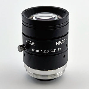
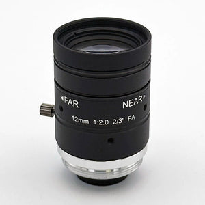
1D and 2D label reading on a line CIL122 IR-corrected M12, 12mm The longer 12mm EFL holds pixel count on the code when the camera stands back over a conveyor, and the IR-corrected design keeps focus stable if NIR illumination is added. F/2.0 fixed, 43° FoV at a 9.2mm image circle. View CIL122
Close-range DPM and small codes CIL052 low distortion M12, 5.2mm A short EFL at a close working distance puts high pixel density on small dense codes, and -0.1% rectilinear distortion keeps modules decodable when they land near the frame edge. F/3.4 fixed, up to 1/1.8" sensors. View CIL052
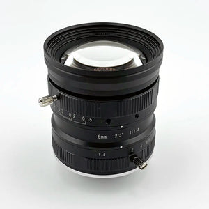
OCR and document scanning CIL522 C-mount C-mount, 12mm Flat field and 0.4% distortion across an 11.4mm image circle suit full-page geometry, and the F/1.4 adjustable iris trades aperture for depth of field on curved labels or uneven documents. Up to 2/3" sensors. View CIL522

One boundary worth stating: for high-accuracy DPM gauging, where the job is measuring part dimensions rather than decoding a mark, telecentric lenses from vendors such as Opto Engineering or Edmund Optics are the right tool. Commonlands does not sell telecentric lenses, and none of the lenses above are telecentric or sealed.

An overhead M12 camera images a printed page for document scanning and OCR
Even flat-field illumination keeps characters sharp from corner to corner.

자주 묻는 질문

How do I choose a lens for barcode reading in machine vision?

Start with the minimum bar width (X dimension for 1D codes) or module size (for Data Matrix and QR) at the real working distance. Calculate the focal length that produces enough pixels across that feature: a minimum of 10 pixels per bar for reliable 1D reading, and 8 pixels per module side as the production target for Data Matrix or QR (6 px marginal lower bound). Then confirm depth of field covers your working-distance tolerance, distortion is acceptable near the image edges, and exposure time is short enough to prevent motion blur at line speed.

What lens should I use for OCR in machine vision?

Start with a fixed focal length lens sized to put at least 20 pixels across the x-height of the smallest character. A low-distortion M12 lens such as the CIL052 works well at moderate working distances for embedded OCR and label reading. When the camera must stay back (overhead conveyors, distant packages), a longer-focal-length lens preserves character size on the sensor. C-mount is preferred when an adjustable iris is needed for depth-of-field control or the sensor is larger than the specific M12 lens's image circle covers, typically above 1/1.8 inch for most M12 models and above 1/1.7-1/1.6 inch for the largest-coverage M12 designs.

What lens should I use for document scanning in machine vision?

Start with document size, working distance, and sensor size, then calculate the focal length so the full page fills the sensor field at that working distance. Choose a low-distortion fixed focal lens matched to those numbers rather than the widest lens that technically fits. For embedded setups, a low-distortion M12 lens such as the CIL052 is practical; for bench or archival scanning where aperture control and larger sensors matter, a C-mount lens gives more control.

What lens is needed for iris recognition?

Iris recognition needs an NIR-transmitting lens paired with roughly 850nm illumination and a matching bandpass filter, sized to put enough pixels across the iris diameter (commonly cited targets run from about 100 to 200 pixels across the iris for standards-grade capture). The lens and filter stack must pass 850nm efficiently; a standard visible-only IR-cut path blocks the wavelength the sensor needs. See the Commonlands NIR imaging guide for the full filter and illumination stack.

How many pixels does a barcode module need?

For 1D barcodes, a minimum of 10 pixels across the narrowest bar element (the X dimension) is the standard production target, with 6-8 pixels as a marginal lower bound. For 2D Data Matrix and QR codes, 8 pixels per module side on each axis is the production target, with 6 pixels as a marginal lower bound; 3-4 pixels per module can work in controlled lab conditions but leaves little margin for blur, focus variation, or contamination.

How many pixels should I have across each character for OCR?

A common engineering rule is a minimum of 20 pixels across the x-height of each character for reliable OCR. Under 10 pixels per character height, accuracy degrades significantly regardless of the software used. Divide the sensor pixel count in the relevant axis by the scene dimension in that axis, multiply by character height, and compare the result to the 20-pixel target before finalizing focal length.

Is rolling shutter acceptable for document scanning?

Rolling shutter is often acceptable for document scanning because the scene is static. Rolling shutter captures rows sequentially, so motion artifacts appear when the object or camera moves during capture. A document lying flat on a platen does not move, so rolling shutter does not introduce the skew or wobble it would in a moving-conveyor application; the remaining static-scene concern is banding under pulsed or flickering illumination, which steady light or a strobe held on across the full readout avoids. Use global shutter if the document is transported through a feeder or the camera cannot guarantee the document is stationary before capture.

What is different about reading 1D barcodes versus Data Matrix codes?

1D barcodes encode data in bars along one axis and can be decoded from a single scan line, tolerating blur in the perpendicular direction; the driving parameter is the X dimension, the narrowest bar width. Data Matrix and QR codes encode data in both axes, so every module must be resolvable in two directions, which raises requirements on MTF uniformity, distortion, and focus quality across the full field the code occupies.

What is needed for face recognition camera optics?

Face recognition needs even illumination across the capture volume, low distortion so facial geometry is not warped near the frame edges, and enough pixels across the interpupillary distance or face width for the matching algorithm in use. Many access-control and identity systems add NIR illumination around 850nm so capture is consistent regardless of ambient visible lighting, which requires a lens and filter path that transmits that wavelength.

Does distortion matter for barcode reading?

It depends on the application. Straight-line decoding algorithms tolerate moderate distortion near the center of the image, but distortion deforms bars and modules near the edges, which can cause decode failures when codes land in the corners of the field. Low-distortion lenses matter most when codes appear at the image edges, the same lens is used for geometric measurement, or the image is not software-corrected before decoding.

When should I use M12 versus C-mount for data-capture applications?

M12 lenses are the practical default for barcode, OCR, and document capture on compact cameras with sensors up to what the specific M12 lens's image circle covers (typically up to about 1/1.8 inch for most models and up to 1/1.7-1/1.6 inch for the largest-coverage M12 designs), offering low-distortion designs at lower cost and smaller size. C-mount lenses make sense when the sensor is larger than the M12 lens's coverage, when an adjustable iris is needed to tune depth of field for uneven surfaces or curved labels without changing the lighting rig, or when the application needs a longer focal length than the M12 range covers well.

What aperture should I use for barcode or document reading?

Use the widest aperture that keeps the entire feature in acceptable focus across the expected working-distance range, then stop down if depth of field is insufficient. Stopping down extends depth of field but reduces exposure, forcing a longer shutter time or brighter lighting, and runs into a diffraction floor at very small apertures. M12 lenses typically do not provide an adjustable iris; the aperture is fixed by the optical design in nearly all models. C-mount lenses with an iris ring let engineers tune depth of field in the field, which is practical because machine vision illumination is usually programmable.

Need help matching a lens to a data-capture application?

Describe the code type, character size, document geometry, or biometric modality, along with working distance, sensor, and line speed. Commonlands engineering can work through pixel coverage, depth of field, distortion, and illumination requirements before you commit to hardware.