

카메라 모듈을 위한 능동 정렬: 센서 기울기, 6-DOF 오차 예산 및 UV 경화 조립
This guide explains what active alignment is, why thread-and-lock assembly runs out of adjustment at high resolution, how to build the 6-DOF error budget, and how the UV-cure process locks lens-to-sensor position.

Active alignment (AA) positions the lens relative to the powered image sensor in up to six degrees of freedom while scoring through-focus sharpness on live video, a system SFR measurement of the assembled lens and sensor rather than the lens MTF a datasheet publishes, then locks the position with UV-cure adhesive. It replaces thread-and-lock assembly when corner focus must survive tilt, decenter, and defocus tolerances a threaded interface cannot control.
Sensor alignment is the underlying requirement: nominally the sensor sits perpendicular to the lens optical axis, centered on it, and at the designed axial distance, though a best-fit alignment may hold a deliberate offset. This guide covers both, plus the diagnostics that separate real misalignment from field curvature.
‘능동 정렬’이란 무엇인가요?
The word "active" distinguishes the process from passive assembly, which relies on dimensional tolerances: machine the parts accurately, stack them, and accept the optical result. Active alignment closes the loop on the measured image instead. Because the sensor is powered and streaming, the machine aligns each lens to the true position of that specific die, absorbing the placement and stack-up tolerances a threaded build leaves uncorrected.
The move is rigid-body, so element tilt and decenter inside the lens, wedge in the sensor package or cover glass, local die warp, and the design's own field curvature all survive it, and adhesive shrinkage can add drift after cure. The station balances the field against those residuals rather than removing them. The MTF curve guide explains the measurement. Active alignment runs it inside the assembly loop, on the module's own sensor, for every unit built.
Camera module makers call it AA. Optics labs call it active lens-to-sensor alignment. Commonlands does not run it. Its San Diego module line focuses each lens on its thread, as described under camera module assembly below.
센서 정렬이란 무엇인가요?
Die placement, solder height, PCB flatness, holder molding, and thread engagement all affect alignment. Their combined variation can move the sensor outside the lens's acceptable focus range. Geometric calibration cannot refocus a blurred image. Mechanical rework or a lens with more focus tolerance may help. Image-circle coverage and back focal distance establish basic compatibility, but a through-focus measurement is needed to check the assembly's focus margin.
틸트
Tilt means the sensor plane is not orthogonal to the optical axis, so one region sits closer to the in-focus image surface than the opposite. The result is a focus gradient: one side sharp, the other soft.
A clean linear gradient points at tilt, the most diagnosable error, but not necessarily at the sensor: package wedge, a tilted lens element, a skewed holder, or a chart that is not square to the axis all read the same way. Square the target and the fixture first, then run the lens-rotation test in the FAQ below.
디센터
Decenter is lateral displacement of the sensor from the optical axis. The lens's best-corrected field region shifts relative to the pixel array, so sharpness goes asymmetric and relative illumination falls off around a center the datasheet does not predict.
회전
Rotation is a spin of the sensor about the optical axis. For a rotationally symmetric lens on a rectangular sensor, it rarely changes image quality. It matters for geometry: measurement coordinates rotate and the pixel-to-physical mapping turns with them. A stereo rig keeps its physical baseline, since rotation does not move the optical centers. What changes is each camera's extrinsic orientation, which breaks rectification because the epipolar lines no longer follow sensor rows.
Z축 높이 오차
Z-height error places the sensor at the wrong axial distance, moving the focus conjugate off the intended working distance. It produces symmetric defocus, so refocusing resolves it. The giveaway is sharp focus landing at a working distance other than spec. Back focal length tolerances are the usual cause, covered in the back focal length guide.
고해상도에서는 왜 나사와 잠금 장치 조합만으로는 충분하지 않은가요?
A threaded M12 lens controls one degree of freedom: axial position, set by rotating the lens in its holder. Tilt, decenter, and rotation stay wherever the mechanical tolerances put them. Whether that matters depends on the depth of focus, which the working f-number and the allowed blur circle set together. Near 1.5µm pixels and below, that budget can shrink until thread clearance and board stack-up alone consume the corner focus allowance.
The M12 x 0.5 pitch moves the lens 500µm per full turn, so the thread sets axial focus with micrometer sensitivity. The clearance that lets it turn, set by the ISO metric tolerance classes, also lets the locked lens sit off-axis and tilted, and thread adhesive freezes whatever pose that clearance allowed.

Thread clearance is one contributor among several. Every source above stacks into the lens-to-pixel position. The image-side tolerance for that stack is the depth of focus (distinct from object-side depth of field, covered in the depth of focus section of the DOF guide):
Stopping down raises depth of focus in proportion to the working f-number and hides residual misalignment. Legitimate when illumination allows, but it trades light. For object-side planning, use the depth of field calculator.
6-DOF 오차 예산이란 무엇인가요?
A camera module has six rigid-body degrees of freedom between lens and sensor: three translations (X, Y, Z) and three rotations (θx and θy tip and tilt, θz rotation). Z sets focus, X and Y set decenter, tip and tilt set the corner focus gradient, and θz sets geometric registration. An error budget gives each axis a tolerance whose combined image-side effect stays inside the depth of focus at every field point.
Start from the allowed blur circle c, set by pixel pitch and the detection task. Compute the depth of focus, then allocate it: Z placement error, tilt-induced corner shift, and the lens's field curvature residual must sum within δ at every field point. Independent random sources like die placement and holder squareness combine by root-sum-square. The systematic curvature residual adds directly.
Tilt enters that sum through the image height: a tip or tilt of α radians carries one corner toward the lens and the opposite away by the same amount.
Work it on a 1/2.3-inch sensor, where the corner image height r is about 3.95mm. At a working f-number of 2.0 with c = 3µm the budget is δ = ±6µm, so a 1.5 mrad tilt, about 0.09 degrees, lands one corner at +δ and its diagonal partner at -δ. Nothing is left for Z placement or field curvature, which is why tip and tilt take the largest share.
The budget is verified with a through-focus sharpness sweep at the center and four corners: on a threaded build it qualifies the design's passive tolerances, and on an aligned line it runs on every unit as the alignment criterion.
어떤 경우에 카메라에 나사산 방식의 M12 구조 대신 능동 정렬 방식이 필요한가요?
Prototype with a threaded M12 build first: it proves the sensor, field of view, illumination, and processing chain with catalog parts and no tooling. Move to active alignment when corner MTF, unit-to-unit consistency, or a tilt-sensitive wide-angle design pushes yield below target with passive tolerances.
The threaded workflow is fast: pick a stock lens from the M12 lens collection, thread it into a holder, focus on a live image, and lock it. Modules with a more forgiving focus budget routinely ship threaded and hold spec.
C-mount systems mostly sit outside this decision, though not because the lens refocuses. The camera vendor sets the sensor pose behind a standardized 17.526mm flange, so the integrator has no lens-to-sensor alignment to make. Refocusing, by cam on many industrial C-mount designs or by unit focus on others, moves the focus conjugate only: sensor tilt, decenter, rotation, and package wedge still take mechanical rework, and stereo extrinsics still need calibration. Active alignment is a board-level module process.

| 요인 | 나사산이 있고 잠금 장치가 있는 M12 | 능동 정렬 |
|---|---|---|
| 제어되는 자유도 | Z축만, 나사산 회전 방식 | 모두 6개까지 |
| 코너 초점 일관성 | 수동적 적층 공차의 제약으로 인해 | Set per unit on the measured sharpness score |
| 장비 | 초점 대상 및 수공구 | AA 스테이션, 접착제 도포, UV 경화 |
| 단가 및 사이클 타임 | 최저 | 더 높은 수준, 거래량에 따라 상각 |
| 재작업 | 스레드락이 경화될 때까지 재조정이 가능합니다 | 접착제 경화 후 영구적 |
| 일반적인 핏 | Prototypes and moderate corner specs. Bigger pixels leave more focus budget | 소형 픽셀 제작, 광각 코너 사양, 스테레오 정렬 |
The two paths share parts: a module prototyped with a stock M12 lens can move to actively aligned production on the same optics, so the qualification work carries over. Threaded builds also carry real volume. Commonlands delivered a 20,000-unit MIPI module program, Sony IMX577 sensors with the CIL227 2.7mm fisheye, on threaded mounts, with each lens focused against live sharpness scores from in-house software.
UV 경화 방식의 능동 정렬 공정은 어떻게 작동하나요?
- Dispense. Adhesive beads go on the holder bond surface or the lens barrel skirt. The glue gap replaces the thread, so it must absorb the full Z tolerance range being corrected.
- Grip and coarse-position. A multi-axis gripper places the lens near nominal. The sensor powers on and streams live video to the alignment software.
- Sweep through focus. The station sweeps the lens through Z, computing a system SFR sharpness score at the center and four corner regions of interest on each frame.
- Optimize the pose. Tip, tilt, X, Y, and Z move until center and corner scores peak inside a common window. The merit function balances the field rather than maximizing the center.
- Cure and verify. UV LEDs gel the joint within seconds while the gripper holds the optimized pose, with the target pre-offset by the characterized cure shrinkage. A thermal post-cure completes cross-linking where the chemistry requires it, then end-of-line through-focus verification.
Adhesive selection drives the process window. UV acrylates cure fastest. Modified epoxies, often dual-cure UV plus thermal, are more stable and reach joints the UV light cannot. All shrink during cure, so production measures the post-cure shift on qualification builds and aims off by it. Particle control matters too: a single fiber under the bond line becomes a permanent tilt.
In a fixed-focus module, curing the joint locks the lens-to-sensor position. Objects remain acceptably sharp over the measured depth of field, rather than at only one distance. An autofocus module can still refocus through its actuator after alignment. Confirm the required object-distance range and focus target before curing a fixed-focus build.
Find lenses for your camera project
Many Commonlands lenses publish MTF and distortion specs, so asymmetric corner degradation stands out against a known baseline. Where that is not enough, order a measured MTF report through the Trioptics HR2 test report.
For a module that will be actively aligned by your module maker, Commonlands can respecify a stock barrel with a bonding flange, a flat shoulder replacing the M12 thread so their AA station can grip, position, and bond the lens. Send the sensor, holder geometry, and volume for a quote.
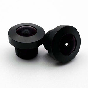
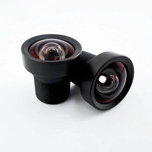
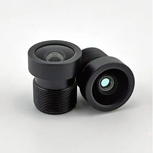
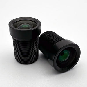
카메라 모듈 조립체
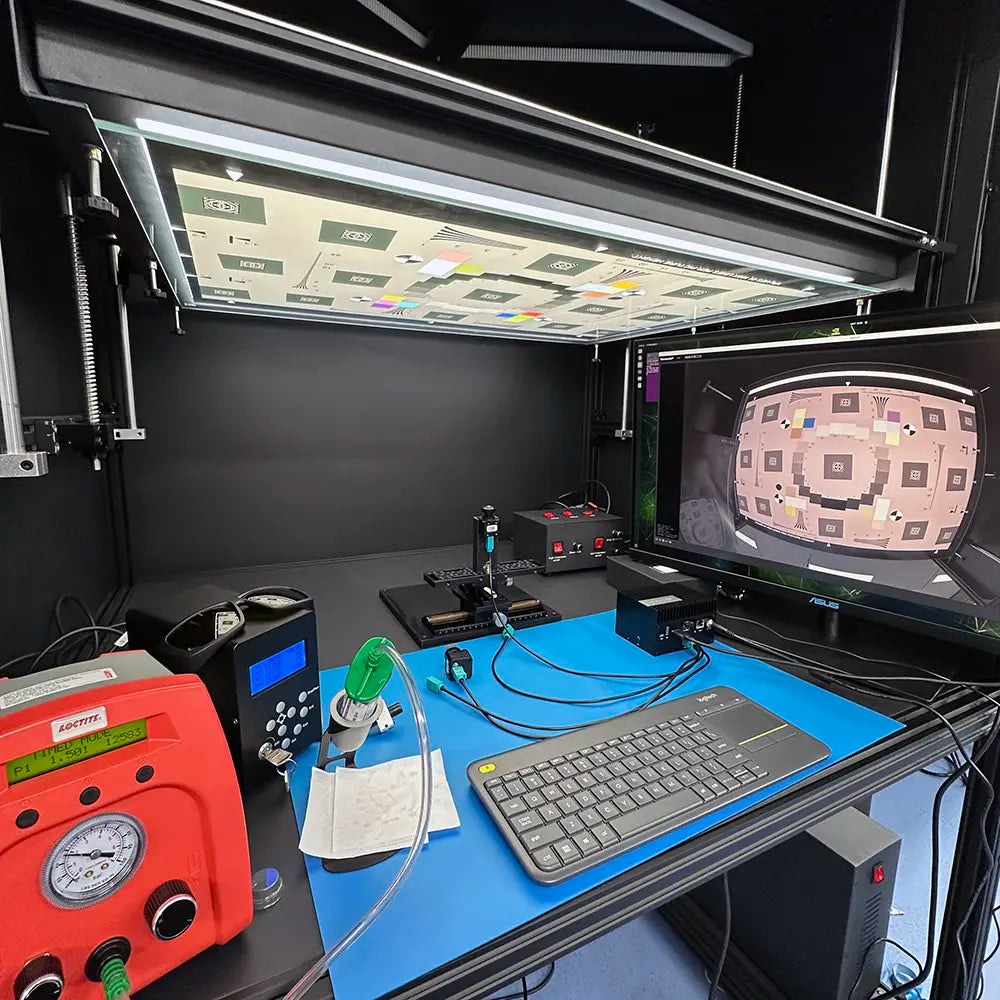
Commonlands assembles camera modules in a Class 1000 cleanroom in San Diego, from consigned-sensor builds at 100 to 100,000 units per year through custom MIPI CSI-2, DVP, and USB development. Modules are focused on the lens thread, not actively aligned, so the design's passive tolerance stack has to close. Automated focusing stations, each running 120 modules per hour, will be online for volume production by the end of 2026.

자주 묻는 질문
카메라 모듈 제조에서 ‘액티브 얼라인먼트’란 무엇인가요?
Active alignment positions the lens relative to the powered image sensor in up to six degrees of freedom while scoring through-focus sharpness on live video, a system SFR measurement rather than the datasheet lens MTF, then fixes the position with UV-cure adhesive. Each module is aligned to its own measured image, absorbing mechanical tolerances that threaded assembly leaves uncorrected. It cannot correct errors inside the lens or sensor package.
카메라 모듈에서 센서 정렬이란 무엇인가요?
Sensor alignment is the mechanical relationship between the image sensor plane and the lens optical axis and image plane. Nominally the sensor sits perpendicular to the axis, centered on it, and at the designed axial distance. Unintended departures degrade performance in ways software cannot recover. A best-fit active alignment may hold a deliberate tilt or offset when the lens carries residual asymmetric error, because the target is balanced field MTF, not geometric perfection.
센서가 기울어져 있는지 어떻게 알 수 있나요?
Capture a flat target squared to the optical axis and measure sharpness at the center and four corners. Tilt anywhere in the stack produces an asymmetric focus gradient, one corner sharp and the diagonal partner soft. Rotate the lens 90 degrees, re-seat the thread, and refocus. If the pattern follows the lens across several rotations, the tilt is in the lens. If it stays put, look at the sensor mounting. Barrel runout and fixture motion also change with the turn, so control them first.
언제 능동 정렬이 필요한가요?
Active alignment is typically necessary when corner requirements exceed what passive tolerances deliver: small pixels (often near 1.5 microns and below, though the trigger is the focus budget and the yield it produces, not the pitch alone), wide-angle fixed-focus modules, stereo rigs needing registration, and volume production where unit-to-unit consistency sets yield. Prototype with a threaded M12 build first and move to active alignment when pilot corner MTF falls short.
소프트웨어로 센서의 기울기를 보정할 수 있나요?
No. Sharpening and deconvolution can raise apparent contrast at moderate spatial frequencies, but they cannot recover content the optics never delivered. Focus information lost to tilt-induced defocus is gone at capture. The fix is mechanical: rework the lens-sensor stack-up or actively align the module during assembly.
카메라 모듈 제작을 계획 중이신가요?
Commonlands manufactures M12, C-mount, and CS-mount lenses, many with published MTF and distortion specs, and assembles camera modules in a Class 1000 cleanroom in San Diego under an ISO 9001:2015 certified quality system. Send your sensor model, resolution target, and volume to engineering@commonlands.com. Stocked lenses ordered before 12 PM PST ship the same day.